Suitable for air quality applications


Overview
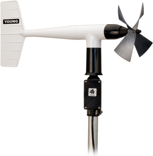
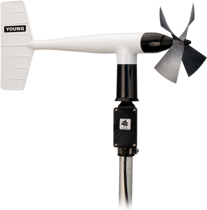
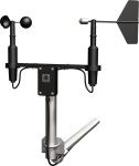
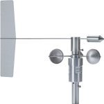
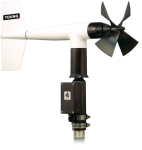
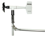
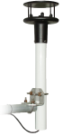
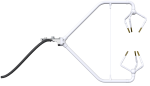
The 05305 is a lightweight, high-performance wind-speed and wind-direction sensor designed specifically for air-quality measurements. It is more responsive but less rugged than the other wind monitors. Manufactured by R. M. Young, this sensor is cabled for use with Campbell Scientific dataloggers.
Read MoreBenefits and Features
- Compatible with most Campbell Scientific data loggers
- Constructed with thermoplastic material that resists corrosion from sea-air environments and atmospheric pollutants
- Lower starting threshold, faster response, and higher accuracy than the other wind monitors
- Meets or exceeds requirements of the following regulatory agencies: U.S. Environmental Protection Agency, U.S. Nuclear Regulatory Agency, and American Nuclear Society
- Compatible with the LLAC4 4-channel Low-Level AC-Conversion Module, which increases the number of anemometers one data logger can measure
- Compatible with the CWS900-series interfaces, allowing it to be used in a wireless sensor network
Technical Description
The 05305 Wind Monitor-AQ is made out of light-weight, UV-stabilized thermoplastic with stainless steel and anodized aluminum fittings. The thermoplastic material resists corrosion from sea air environments and atmospheric pollutants. It uses stainless-steel precision-grade ball bearings for the propeller shaft and vertical shaft bearings.
The 05305 measures wind speed with a helicoid-shaped, four-blade propeller. Rotation of the propeller produces an ac sine wave that has a frequency directly proportional to wind speed. The ac signal is induced in a transducer coil by a six-pole magnet mounted on the propeller shaft. The coil resides on the non-rotating central portion of the main mounting assembly, eliminating the need for slip rings and brushes.
Wind direction is sensed by the orientation of the fuselage-shaped sensor body, which is connected to an internal potentiometer. The datalogger applies a known precision excitation voltage to the potentiometer element. The output is an analog voltage signal directly proportional to the azimuth angle.
Designed specifically for air quality measurements, the 05305 Wind Monitor-AQ provides a lower starting threshold, faster response, and higher accuracy than the other wind monitors. It meets or exceeds the requirements published by the following regulatory agencies:
- U.S. Environmental Protection Agency—Ambient Monitoring Guidelines for Prevention of Significant Deterioration (PSD) and On-Site Meteorological Instrumentation Requirements to Characterize Diffusion from Point Sources
- U.S. Nuclear Regulatory Agency—NRC Regulatory Guide 1.23 Meteorological Programs in Support of Nuclear Power Plants
- American Nuclear Society—Standard for Determining Meteorological Information at Nuclear Power Plants
Images
Related Products

Compatibility
Mounting
The 05305 can be attached to a crossarm via a 17953 NU-RAIL fitting or CM220 Right Angle Mounting Bracket. Alternatively, it can be attached to the top of a CM106B or a stainless-steel tripod via the CM216 Sensor Mounting Kit.
Programming
The 05305's propeller is measured by the PulseCount Instruction in CRBasic and by Instruction 3 (Pulse Count) in Edlog. The wind vane is measured by the BrHalf Instruction in CRBasic and by Instruction 4 (Excite-Delay-SE) in Edlog. The measurements are typically processed for output with the Wind Vector instruction (not present in the CR500 or CR9000 but is present in the CR9000X).
Specifications
| Applications |
|
| Sensor | Helicoid-shaped, 4-blade propeller and fuselage-shaped sensor body |
| Measurement Description | Wind speed and direction |
| Operating Temperature Range | -50° to +50°C (assuming non-riming conditions) |
| Mounting Pipe Description |
|
| Housing Diameter | 5 cm (2.0 in.) |
| Height | 38 cm (15.0 in.) |
| Length | 65 cm (25.6 in.) |
| Propeller Diameter | 20 cm (7.9 in.) |
| Weight | 1.1 kg (2.5 lb) |
Wind Speed |
|
| Range | 0 to 50 m/s (0 to 112 mph) |
| Accuracy | ±0.2 m/s (±0.4 mph) or 1% of reading |
| Starting Threshold | 0.4 m/s (0.9 mph) |
| Distance Constant | 2.1 m (6.9 ft) 63% recovery |
| Output |
ac voltage (three pulses per revolution) 90 Hz (1800 rpm) = 9.2 m/s (20.6 mph) |
| Resolution | (0.1024 m s-1) / (scan rate in seconds) or (0.2290 mph) / (scan rate in seconds) |
Wind Direction |
|
| Mechanical Range | 0 to 360° |
| Electrical Range | 355° (5° open) |
| Accuracy | ±3° |
| Starting Threshold | 0.5 m/s (1.0 mph) at 10° displacement |
| Distance Constant | 1.2 m (3.9 ft) 50% recovery |
| Damping Ratio | 0.45 |
| Damped Natural Wavelength | 4.9 m (16.1 ft) |
| Undamped Natural Wavelength | 4.4 m (14.4 ft) |
| Output |
|
| Voltage | Power switched excitation voltage supplied by data logger |
Resources and Links
Videos & Tutorials

FAQs for
Number of FAQs related to 05305-L: 8
Expand AllCollapse All
-
This depends on what is broken. Typically, Campbell Scientific can repair the unit, and the user does not have to purchase a new one.
-
The measurement instructions will likely remain the same. However, in addition to the multiplier and offset, the type of pulse may change for the wind speed, and the excitation voltage may change for the wind direction. For an explanation of how the data logger needs to be programmed, see the instruction manual.
-
Orientation of the wind monitor is done after the data logger has been programmed, and the location of True North has been determined. True North is usually found by reading a magnetic compass and applying the correction for magnetic declination, where magnetic declination is the number of degrees between True North and Magnetic North. Magnetic declination for a specific site can be obtained from a USFA map, local airport, or through a computer service.
-
The short answer is less than 0.01 mA. The wind speed signal requires no power. The wind direction portion of the sensor only uses a maximum of 0.5 mA when excited with 5 Vdc, and then it is only on for 0.016 s for every measurement. When the wind direction is measured every second (typical), the average current drain is less than 0.01 mA.
-
The information included on a calibration sheet differs with each sensor. For some sensors, the sheet contains coefficients necessary to program a data logger. For other sensors, the calibration sheet is a pass/fail report.
-
To incorporate a sensor that is compatible with wireless sensor interfaces into a wireless network, a CWS900-series wireless sensor interface is needed, as well as an A205 CWS-to-PC interface to configure it.
-
- Using Short Cut, click the applicable wind direction sensor in the Selected Sensors list of the Outputs screen.
- The two output options enabled are Sample and WindVector. Select WindVector.
- The WindVector instruction has output options. Select an option with mean wind direction in it.
Privacy Policy Update
We've updated our privacy policy. Learn More
Cookie Consent
Update your cookie preferences. Update Cookie Preferences