
Can be used in a variety of applications


Overview
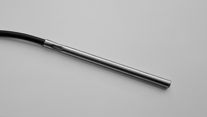
The 109 is a rugged, accurate probe that measures air, soil, and water temperature for a variety of applications. It consists of a thermistor encapsulated in an epoxy-filled aluminium housing. The housing protects the thermistor, allowing the 109 to be buried or submerged. The 109 measures from -50° to +70°C.
Read MoreBenefits and Features
- Versatile product—measures air, soil, or water temperature
- Wide temperature measurement range
- Compatible with most Campbell Scientific data loggers
- Easy to install or remove
- Durable
Technical Description
The 109 consists of a thermistor encapsulated in an epoxy-filled aluminium housing. The housing protects the thermistor allowing it to be buried in soil or submerged in water.
This probe outputs a 0 to 2.2 V signal when using 2500 mV excitation.
Images
Compatibility
Please note: The following shows notable compatibility information. It is not a comprehensive list of all compatible products.
Dataloggers
| Product | Compatible | Note |
|---|---|---|
| CR1000 (retired) | ||
| CR300 (retired) | ||
| CR3000 | ||
| CR310 | ||
| CR350 | ||
| CR6 | ||
| CR800 (retired) | ||
| CR850 (retired) |
Additional Compatibility Information
Datalogger Considerations
The 109 was designed specifically for our CR200(X)-series dataloggers. Other dataloggers may measure the 109 probe, but the 107 and 108 temperature probes are more often used for dataloggers that can measure them.
Programming
The instruction set for our CR800-series, CR1000, and CR3000 dataloggers contains the Therm109 instruction for measuring the 109 probe. Programming is more complicated for other dataloggers because they must use generic measurement instructions.
Installation Considerations
Air Temperature
When exposed to sunlight, the 109 must be housed in a radiation shield. It is typically housed in a 41303-5A 6-plate naturally aspirated shield. It may also be housed in a 41003-5 10-plate shield if a 41322 Adapter Plate is used. The radiation shield mounts to a mast, tower leg, or crossarm.
Soil Temperature
The 109 is suitable for shallow burial only. Placement of the cable inside a rugged conduit may be advisable for long cable runs—especially in locations subject to digging, mowing, traffic, use of power tools, or lightning strikes.
Water Temperature
The 109 can be submerged to 50 ft. Please note that the probe is not weighted. Therefore, the installer should either add a weighting system or secure the probe to a fixed, submerged object, such as a piling.
Specifications
| Output | Analog |
| Operating Temperature Range | -50° to +70°C |
| Sensor Description | Measurement Specialties™ 10K3A1iA Thermistor |
| Tolerance | ±0.2°C (over 0° to 70°C range) |
| Temperature Measurement Range | -50° to +70°C |
| Steinhart-Hart Equation Error | ≤ 0.03°C (-50° to +70°C) |
| Interchangeability Error | ±0.1°C (over 0° to 70°C range increasing to ±0.5°C at -50°C) |
| Time Constant in Air | 30 to 60 s (in a wind speed of 5 m s-1) |
| Maximum Submergence | 15 m (50 ft) |
| Maximum Cable Length | 305 m (1000 ft) |
| Probe Length | 10.4 cm (4.1 in.) |
| Probe Diameter | 0.76 cm (0.3 in.) |
| Weight | 136 g (5 oz) with 3.05-m (10-ft) cable |
Resources and Links
Product Brochures
Manuals
Compliance
Listed Under
FAQs for
Number of FAQs related to 109: 5
Expand AllCollapse All
-
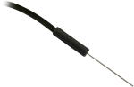
The thermistor is located approximately 3 mm (0.125 in.) back from the probe tip.
-
When these sensors are purchased, the following calibration services are offered: TEMPCAL and TEMPCAL2.
- TEMPCAL provides a single-point calibration and a calibration certificate. The single-point calibration determines the offset at 25°C with an uncertainty of ±0.05°C.
- TEMPCAL2 provides a two-point calibration and a calibration certificate. The two-point calibration determines offsets at 30°C and 65°C with an uncertainty of ±0.05°C.
For both of these services, calibration can be made at different values if it is requested by the purchaser at the time of purchase. In addition, both of these calibration services can be requested after sensor purchase using a return material authorization (RMA) number. To request an RMA number, refer to the Repair and Calibration page.
-
The sensor/probe consists of a non-linear thermistor configured with a precision resistor in a half-bridge circuit, as shown in the product’s manual:
- Model 107 Temperature Probe Instruction Manual
- Model 108 Temperature Probe Instruction Manual
- 108-LC Temperature Probe for MetData1 Instruction Manual
- Model 109 Temperature Probe Instruction Manual
To measure the sensor/probe, the measurement device has to provide a precision excitation voltage (Campbell Scientific data loggers use 2000 mV), measure the voltage across the precision resistor, determine the thermistor resistance (Ohm's law), and convert the resistance to temperature using the Steinhart-Hart equation.
The Steinhart-Hart equation is 1/T = A + Bln(R) + C(ln(R))3 where:
- T is the temperature in Kelvin
- R is the resistance at T in ohms
- A, B, and C are the Steinhart-Hart coefficients, which vary depending on the temperature range of interest, as well as the type and model of the thermistor
For the 107-L, 107-LC, 108-L, and 108-LC, the following are the coefficients for the Steinhart-Hart equation:
- A = 8.271111E-4
- B = 2.088020E-4
- C = 8.059200E-8
For the 109-L, the following are the coefficients for the Steinhart-Hart equation:
- A = 1.129241E-3
- B = 2.341077E-4
- C = 8.775468E-8
-
Note the difference between calibration and a field check. Calibration cannot be done in the field, as it requires an experienced technician and specialized equipment.
Field checks of measurements can be done to determine if the data make sense with the real-world conditions. Follow these steps to field check a sensor:
- Find a second sensor of the same type as the installed sensor whose data is in question. The second sensor will be used as a benchmark sensor and should be known to be accurate or recently calibrated.
- At the site, take readings using both sensors under the same conditions. The best practice is to measure both sensors side-by-side at the same time. Note that the sensors will never have the exact same measurement.
- Depending on the sensor model, if the difference in the readings of the installed and benchmark sensors is greater than the sum of the accuracies for both sensors, either return the installed sensor to Campbell Scientific for calibration or replace the appropriate chip.
- The 107, 108, 109, 110PV-L, and BlackGlobe-L temperature sensors can be calibrated.
- The HC2S3-L and HMP155A-L temperature and relative humidity sensors can be calibrated.
- The CS215-L has a replaceable chip for temperature and relative humidity. For more information, refer to the “Maintenance and Calibration” section of the CS215 instruction manual.
- The HMP60-L has a replaceable chip for relative humidity only. For more information, refer to the “Maintenance” section of the HMP60 instruction manual.
-
To incorporate a sensor that is compatible with wireless sensor interfaces into a wireless network, a CWS900-series wireless sensor interface is needed, as well as an A205 CWS-to-PC interface to configure it.
Case Studies
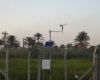
Overview Iraq’s Ministry of Agriculture has deployed a nationwide network of solar-powered, satellite-linked agrometeorological stations. The......read more

Due to its geographical position close to the Black Sea, the local climate in Moldova......read more
The Problem—How to optimize green-roof performance The University of Toronto's Green Roof Innovation Testing Laboratory (GRIT......read more
Privacy Policy Update
We've updated our privacy policy. Learn More
Cookie Consent
Update your cookie preferences. Update Cookie Preferences