This product is not available for new orders. We recommend ordering: TDR200.

| Services Available |
|---|
Overview
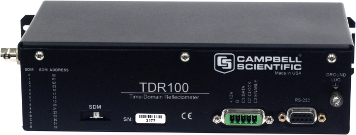
The TDR100 Time-Domain Reflectometer is the core of the Campbell Scientific time-domain reflectometry system. This system is used to accurately determine soil volumetric water content, soil bulk electrical conductivity, rock mass deformation, or user-specific time-domain measurement. Up to 16 TDR100s can be controlled using a single Campbell Scientific datalogger. PC-TDR software is used with our TDR100-based systems during system setup and troubleshooting. It can be downloaded from the Downloads section of the web page.
Read MoreBenefits and Features
- Compact, low-cost reflectometer
- Designed for use in remote applications
- Determines volumetric water content and electrical conductivity in soil and other porous media
- Compatible with CR800, CR850, CR1000, and CR3000 dataloggers
Technical Description
The TDR100 (1) generates a short rise time electromagnetic pulse that is applied to a coaxial system that includes a TDR probe for soil water measurements and (2) samples and digitizes the resulting reflection waveform for analysis or storage.
The elapsed travel time and pulse reflection amplitude contain information used by the on-board processor to quickly and accurately determine soil volumetric water content, soil bulk electrical conductivity, rock mass deformation or user-specific, time-domain measurement.
The data logger collects a 250-point waveform and analyzes it in approximately two seconds. Each waveform can have up to 2,048 data points for monitoring long cable lengths used in rock mass deformation or slope stability. Averaging up to 128 readings makes accurate measurements possible in noisy environments.
Images
Compatibility
Please note: The following shows notable compatibility information. It is not a comprehensive list of all compatible products.
Dataloggers
| Product | Compatible | Note |
|---|---|---|
| CR1000 (retired) | ||
| CR200X (retired) | ||
| CR216X (retired) | ||
| CR3000 | ||
| CR5000 (retired) | ||
| CR800 (retired) | ||
| CR850 (retired) | ||
| CR9000X (retired) |
Additional Compatibility Information
Data Logger Considerations
To control the TDR100, the data logger uses TDR100 instruction in CRBasic or Instruction 119 in Edlog. All CR800-series, CR1000, and CR3000 operating systems (OS) are compatible with the TDR100. The CR10X operating system (OS) should be version 1 rev. 13 or higher and the CR23X OS should be version 1 rev. 10 or higher.
Enclosure Considerations
The TDR100 requires a desiccated, non-condensing environment; a Campbell Scientific enclosure is recommended. The TDR100's case has mounting flanges for attachment to the 1 in.-on-center hole grid of Campbell Scientific enclosures.
Specifications
| Pulse Generator Output | 250 mV into 50 Ω |
| Output Impedance | 50 Ω ±1% |
| Time Response of Combined Pulse Generator & Sampling Circuit | ≤ 300 ps |
| Pulse Length | 14 µs |
| Timing Resolution | 12.2 ps |
| Waveform Averaging | 1 to 128 |
| Electrostatic Discharge Protection | Internal clamping |
| Power Supply |
Unregulated 12 V
(9.6 to 16 V) 300 mA maximum |
| Operating Temperature Range | -40° to +55°C |
| Pulse Generator Aberrations |
|
| Dimensions | 23.6 x 5.9 x 12.6 cm (9.3 x 2.3 x 5.0 in.) |
| Weight | 726 g (1.6 lb) |
Waveform Sampling |
|
| -NOTE- |
20 to 2048 waveform values over chosen length Distance is Vp=1. Time is one-way travel. |
| Range |
|
| Resolution |
|
Current Drain |
|
| During Measurement | 270 mA |
| Sleep Mode | 20 mA |
| Standby Mode | 2 mA |
Resources and Links
Product Brochures
Downloads
TDR100 OS v.0.9724 (60 KB) 15-08-2012
Current TDR100 Operating System. PC-TDR must be connected to TDR100.PC-TDR v.3.0 (7.34 MB) 15-12-2016
Support software designed for the TDR200 and is also compatible with the retired TDR100 Time-Domain Reflectometer.
FAQs for
Number of FAQs related to TDR100: 17
Expand AllCollapse All
-
Theoretically, yes, this can be done. However, it is more common to use a second data logger both for resilience reasons and because there are advantages in keeping TDR cables short. It is best to distribute the systems across the test site rather than trying to centralize everything.
-
Campbell Scientific offers six soil probes that have different rods and connector cables, allowing them to be used in diverse soil types and with a variety of cable lengths. For more details, see the listed TDR100 probes.
-
Yes. The data logger can be programmed to store time-series data from the TDR100. The time-series data can then be viewed using PC400 or LoggerNet. For program examples, see the TDR100 Instruction Manual.
-
Slope stability/rock mass deformation instrumentation is used to detect slope movement and rock mass deformation associated with landslide, mining, and construction activities. In many applications, the ground movement readings are processed by a data logger.
Application engineers at Campbell Scientific can provide a list of geotechnical system integrators who can offer guidance and/or support for TDR cable selection, installation, waveform interpretation, and alarm condition set points.
-
Yes. PC-TDR can send control commands to advance through the channels of a SDMX50-series multiplexer. To do this, select Settings | Multiplexer and then add the multiplexers and probes that match the TDR100 system.
-
To understand the readings obtained from a data logger program, it is necessary to see how the TDR100 operates in PC-TDR. Either the TDR100 commands are entered in PC-TDR and the user waits to see the results, or the data logger sends the TDR100 commands and automatically stores the results.
Campbell Scientific suggests initially entering the TDR100 commands in PC-TDR and waiting for the results before writing a data logger program. This allows verification that the TDR100 is operating correctly in PC-TDR. After that has been verified, a data logger program can be created for the TDR100 that sends the commands and stores the results.
-
No, as of September 2014. The PC-TDR support software can be downloaded free-of-charge from the Downloads section of the PC-TDR product page.
-
Both of these are SDM devices. Each SDM device that is connected to a data logger needs a different SDM address (that is, 0 through 15). All SDM devices connect to the CR1000’s 12V, G, C1, C2, or C3 terminals. Up to 15 SDM devices can be connected to one data logger.
For more information, see the Synchronous Devices for Measurement (SDMs) page.
-
Yes. The data logger can be programmed to send commands to the TDR100 and to store the measurement results. A flag can be used in the program to initiate measurement and store these results.
Case Studies
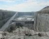
The McCook Reservoir is a ten-billion-gallon reservoir located in La Grange, Illinois. The Metropolitan Water......read more
The McCook Reservoir is a ten-billion-gallon reservoir located in La Grange, Illinois. The Metropolitan Water......read more
The North County Transit District (NCTD) of San Diego County, California, determined that three segments......read more
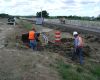
When the Ohio Department of Transportation (Ohio DOT) was preparing to widen Interstate 77, they......read more
Privacy Policy Update
We've updated our privacy policy. Learn More
Cookie Consent
Update your cookie preferences. Update Cookie Preferences