Due to electronic component shortage, this product is temporarily unavailable for online quotes and orders.

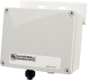
Resides inside weather proof enclosure


Overview
The CS100 measures barometric pressure for the range of 600 to 1100 mb. This range equates to from below sea level (as in a mine) up to 12,000 feet above sea level. Designed for use in environmental applications, the CS100 is compatible with all Campbell Scientific dataloggers.
Read MoreBenefits and Features
- Optimized to mount in Campbell Scientific enclosures
- Low power consumption
- Three-year warranty
- 500 to 1100 hPa (mBar) and 800 to 1100 hPa (mBar) versions also available by special order—contact Campbell Scientific
- Integral switching circuit limits power consumption to measurement cycle
Technical Description
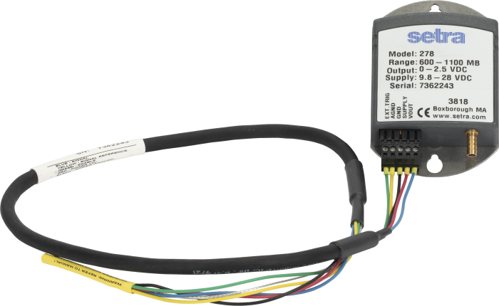
The CS100 is a Campbell Scientific version of Setra's model 278 barometer. It uses Setra’s Setraceram capacitive sensor and IC analog circuit to measure barometric pressure.
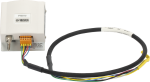
The CS100 is encased in a stainless steel and polyester case fitted with an 1/8 in. barbed fitting for pressure connection. It includes an internal switching circuit that allows the datalogger to power the barometer only during measurement, which reduces power consumption.
Images
Related Products
Compatibility
Please note: The following shows notable compatibility information. It is not a comprehensive list of all compatible products.
Dataloggers
| Product | Compatible | Note |
|---|---|---|
| CR1000 (retired) | ||
| CR1000X (retired) | ||
| CR300 (retired) | ||
| CR3000 | ||
| CR310 | ||
| CR350 | ||
| CR6 | ||
| CR800 (retired) | ||
| CR850 (retired) |
Miscellaneous
| Product | Compatible | Note |
|---|---|---|
| GRANITE 6 (retired) |
Additional Compatibility Information
Data Logger Considerations
A 2.5-ft cable is supplied with the sensor for connection to the data logger. The cable connects to a control port, single-ended analog input terminal, 12 V power terminal, and ground terminal on the data logger.
Mounting
The CS100 is typically mounted next to the data logger inside an ENC12/14 or larger enclosure. The very small ENC100 is available for housing the CS100 separately, in its own enclosure.
Specifications
| Measurement Description | Barometric pressure |
| Signal Type/Output | Analog voltage |
| -NOTE- | 1 hPa = 1 mBar |
| Pressure Range | 600 to 1100 hPa |
| Long-Term Stability | ±0.1 hPa per year |
| Response Time | < 100 ms |
| Resolution | ±0.01 hPa |
| Excitation | 9.5 to 28 Vdc |
| Elevation | ~609.6 m (2,000 ft) below sea level (as in a mine) to 3,657.6 m (12,000 ft) above sea level |
| Accuracy |
|
| Linearity | ±0.4 hPa |
| Hysteresis | ±0.05 hPa |
| Repeatability | ±0.03 hPa |
| Signal Output | 0 to 2.5 Vdc |
| Warm-up Time | < 1 s |
| External Trigger Voltage |
|
| Current Consumption |
|
| Temperature Range | -40° to +60°C |
| Cable Diameter | 0.8 cm (0.3 in.) |
| Cable Length | 0.8 m (2.5 ft) |
| Dimensions | 9.1 x 6.1 x 2.5 cm (3.6 x 2.4 x 1.0 in.) |
| Weight | 135 g (4.8 oz) |
Resources and Links
Product Brochures
FAQs for
Number of FAQs related to CS100: 9
Expand AllCollapse All
-
In most cases, enclosures and buildings have enough little spaces for the pressure to stay at equilibrium with the outside pressure. Therefore, the sensor does not need to be vented to the outside. It is possible, however, that the rate at which the pressure equalizes is slowed by being in an enclosure, but the rate change usually is not noticeably significant.
If the sensor resides in an absolutely air-tight environment, and the pressure outside this environment needs to be measured, then the sensor will need to be vented to the outside. However, venting to the outside may change the rating of the enclosure or associated inside environment.
-
Either the CS100 or the CS106 can fit inside an ENC100. For more information, refer to the Specifications information on the ENC100 product page.
-
The manufacturer recommends calibration on a yearly basis. However, conformance to published standards or regulations may require this on a more frequent basis.
-
For a reading in millibars, the multiplier is 0.240, and the offset is 500. To convert the millibar reading to different units, add an equation to the code.
To correct the pressure to sea level, see the “Correcting Pressure to Sea Level” section in the CS100 instruction manual or in the CS106 instruction manual. Alternatively, use Short Cut for Windows to generate the program, and, when prompted, enter the appropriate site elevation.
-
Yes, but only if certain conditions are met:
- The sensor resides in a non-condensing environment.
- The vent tube accessing the high humidity environment is extremely well desiccated to keep any moisture from reaching the sensor’s components. Moisture in the sensor will damage the sensor, often to an un-repairable state.
-
Noisy measurements may be caused by several factors:
- The sensor was not allowed to warm up adequately.
- The sensor is placed in an electrically noisy environment, which makes other analog measurements noisy.
- The power supply for the sensor or station is dirty. (There is not a clean regulated voltage.)
-
Generally, these sensors are designed to measure the pressure of the environment where they are installed. The CS100 or CS106 can measure the air pressure within a snowpack if the enclosure is adequately sealed away from the snow while allowing the vent to have access to the snow. Note that it may be difficult to accomplish this.
-
It is possible that an older version of Short Cut is being used. Download the latest version of Short Cut.
If the latest version of Short Cut has already been downloaded, open the program.
- Go to Tools | Options and make sure that the Enable Creation of Custom Sensor Files box is checked.
- In the Generic Measurements folder, right-click the type of measurement to be made for the sensor, and select Create Custom Sensor.
- Set the fields according to the sensor’s specification, hide those fields that the user does not need to see after being set, and save the custom sensor file settings with the Save As button.
Case Studies

At the northern edge of Jamaica, fresh water from a limestone aquifer and the Martha......read more
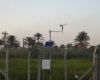
Overview Iraq’s Ministry of Agriculture has deployed a nationwide network of solar-powered, satellite-linked agrometeorological stations. The......read more
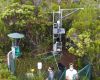
Tropical volcanic islands are biodiversity hotspots where the Critical Zone (CZ) remains poorly studied. In......read more
Everglades National Park is the largest tropical wilderness in the United States and was created......read more
Pont del Petroli was built in the 1960s to enable the transfer of oil from......read more
Articles and Press Releases
Newsletter Articles
Privacy Policy Update
We've updated our privacy policy. Learn More
Cookie Consent
Update your cookie preferences. Update Cookie Preferences